How to test Emergency Lighting
BS5266-1
Emergency lighting should be tested regularly to conform to BS5266-1, with a brief functional test required at least once each month and a full 3hour duration test at least once every year. A visual inspection is also required at least every twelve months. BS5266-1 requires that records of these tests and subsequent repairs or replacements should be kept in a formal log-book.
Across the UK, electricians and emergency lighting maintenance persons generally use three protocols to test emergency lighting. To understand these protocols, it is a pre-requisite to first understand how an emergency light fitting is wired. Note that the guidance below applies to self-contained emergency LED fittings only, they do not apply to central battery-operated emergency light fittings.
Electrical wiring protocols
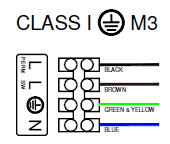
Below is a wiring diagram for a class one maintained LED emergency light fitting. Note the wiring on fluorescent emergency fittings will be the same.
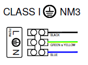
Below is a wiring diagram for a class one non-maintained LED emergency light fitting. Note the wiring on fluorescent emergency fittings will be the same.
L-SW is what you would term its normal mains supply. Any normal sensor or light switch would typically be on this circuit, thus enabling the user to have control over any LED (or Fluorescent) light fitting in its normal operating mode. L-SW must always be wired so that any switching of L-PERM will also disconnect L-SW too, but any switching of L-SW, will not affect the L-PERM.
L-PERM is the permanent live supply and must not have a normal (manually operated) light switch or any type of sensor on it. An (emergency lighting) key-switch is permissible however and the key switch is usually installed on this circuit.
L-PERM has two functions:
a) Supplying the power that keeps the 3hour emergency batteries within each fitting fully charged and why it must not be affected by any switching of L-SW.
b) When no voltage is detected at L-PERM this immediately indicates to the emergency module within the light fitting that it has lost mains power and battery power must now be switched on.
Key-switches for emergency lighting are installed on the permanent live supply to an LED emergency light fitting. When the key switch is actuated, it immediately isolates the emergency fitting, simulating a power failure.
Emergency Key Switch, part No CMA110:
.jpg)
In the UK, these are the three commonly used methods of testing emergency LED lighting:
1) Manual testing of emergency LED (or old fluorescent) light fittings is the most common way to carry out testing and is suitable for more minor installations. A key-switch is commonly used to disconnect the permanent live supply ‘L-PERM’ to any emergency fitting wired to it, simulating a power failure. When this power failure is simulated, and if the fitting is working correctly it will switch to 3hr battery operation and the LED indicator lamp (supplied with every emergency fitting) switches off. Then, when power is restored to L-PERM the LED indicator will switch back on, indicating that the batteries are once again re-charging. Some emergency LED fittings have a manual test button on the fitting itself, negating the need for a Key Switch. It isolates the LED fitting from its permanent live supply which simulates a power failure.
During Test Mode, it is important to ensure the emergency light fitting continues to illuminate in emergency mode for the full duration of its 3 hour test. This is one of the reasons manual testing is not practical in larger buildings.
2) Self-testing emergency LED light fittings are becoming ever more popular, carrying out their very own sequential test without human intervention. A self-test system saves hundreds of expensive labour hours in having to manually test and negates the need for a key-switch and associated electrical wiring. A self-testing emergency LED fitting operates autonomously, carrying out the tests required by BS5266-1 at the appropriate intervals and without communication with adjacent fittings or a primary control point. Manufacturers in the UK typically use three colours of LED indicator to visibly show the status of a Self-test LED fitting. Red indicates a battery or charging fault with yellow indicating an LED fault. If your fitting displays Green, everything is working correctly.
3) An addressable self-test system is a recognised system of testing which engages a leading or central control point module or server which is connected to all the emergency fittings within the installation. Typically, this is by copper cable or RF signal. Every emergency LED fitting is allocated an address and at pre-determined intervals the central module commences a test of each emergency LED fitting, whilst the central module electronically logs the results of the tests. This type of addressable Installation certainly requires the expertise of an accredited Lighting Designer, Electrical Engineer along with persons who can provide guidance in regard modern emergency lighting communication systems.
An addressable self-test system is very much suited to large estates, large projects, colleges, hospitals a university campus and alike.
Who has responsibility for Emergency Lighting?
Within any organisation there should be a responsible person who holds portfolio for emergency lighting in regards the desired LUX levels in an emergency-situation are achieved, as well as ensuring the periodic testing takes place and that key switches are in good working order. This could be a facilities manager, an electrician or perhaps an externally contracted professional. As for any type of emergency lighting install, it is the responsible person’s responsibility to download, interrogate remedy and formally log any issues that arise.
If you would like any more information on products or require an Emergency Lighting design for a building you manage, please give us a call on 0121 439 8010. We have agents across the UK who you can talk to for guidance at no cost.
Thank-you,
Your Electrical Supplier.